

How To Make More Than One Part Move On Solidworks Animation?
Flexible Components, beginning introduced in SOLIDWORKS 2020, let the assembly geometry to simultaneously bulldoze the geometry of a flexible role. This is very advantageous for situations that require a role to dynamically interact with its surroundings, like a compression spring or even a kick for a shifting machinery. The 'Brand Office Flexible' command allows the flexible component to automatically update its position within the assembly without the need to rebuild the assembly each time.
Let's turn our attending to a specific scenario that extends a little across what you might already know. SOLIDWORKS Assistance is a smashing online resource to help explain a feature or control. Hither you can learn how to alter the country of a component in an assembly to become flexible. Maybe you even know how to create your own flexible component. But what virtually the question; "How practise I make my own part flexible? I've already spent a significant amount of fourth dimension modeling this part and I don't want to have to start all over merely considering it wasn't created in the context of an associates."
This is a very off-white question and one that I have encountered while working support recently. Here, I'll explain how you can take your ain part that wasn't previously designed to be a flexible component and make necessary changes to take reward of this capability.
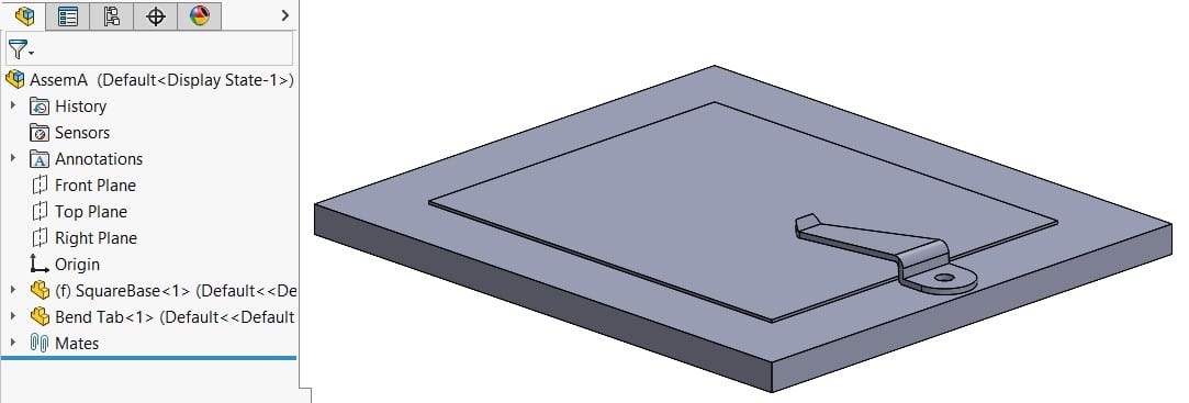
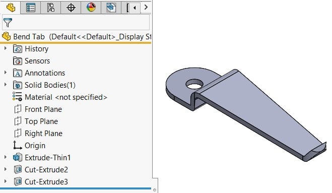
Here is a very quick and basic example of a Bend Tab in an assembly. I just decided that I want this part to update automatically to changes within the assembly. Specifically, I want to emulate a somewhat natural or realistic alter in shape for when the smaller plate increases in thickness. Trust me, there are far amend and more intricate examples, only this helps to get the point across at a basic level.
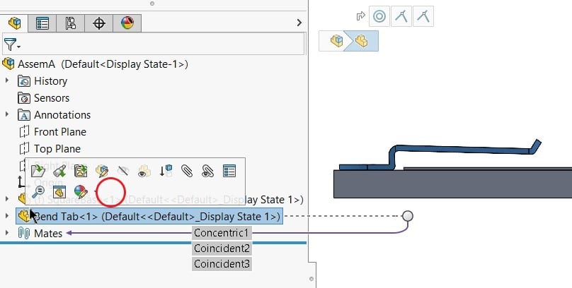
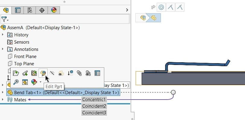
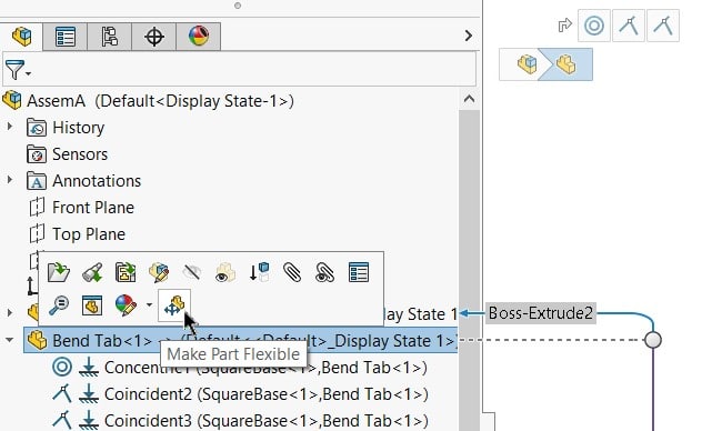
My bend tab was not designed to exist flexible inside an assembly environment. Significant, I never incorporated a degree of liberty to be in-context with another component. I need to ready an external reference so my office can freely interact with position changes in an associates. Equally you tin run across in the image beneath, if I right-mouse click or fifty-fifty left-mouse click the part in the Characteristic Tree to activate the 'Make Part Flexible' control, the icon isn't in that location. The icon will just be present if the selected component is capable of the characteristic in question.
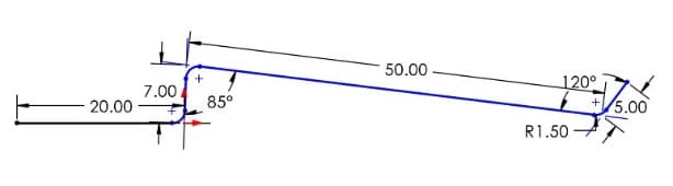
To address the issue of Design Intent, and allow my tab to portray a bending action, I left the sketch Under-Defined to allow flex at the part'south origin. "Shape-shifting" parts should be designed in a fashion that allow desired move without the hinderance of dimensions and relations over-defining the sketch. Sketches for flexible components are not required to exist Nether-Defined merely in this unique example it allows for a dandy graphical representation.
Despite my part having the ability to alter shape, at that place is null present to bulldoze the shape. That is where the external reference comes in but at that place is a specific guild of operations needed.
A flexible component must exist created, or in this case edited, in-context of an assembly. This state of affairs allows the option of an external reference that ultimately drives the dimension of our role. To reach this, offset select the part from the Feature Tree and select 'Edit Part.'
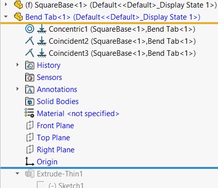
You volition now be editing the part in the context of the associates. The component and all its feature modify to a blue text in the Feature Tree and the 'Edit Part' Icon displays in the upper-right corner of the graphics expanse.
The next footstep, and near of import office to remember to do when editing in-context, is to drag the Rollback Bar to the top before the first feature or sketch. Doing this allows us to successfully create a relation betwixt the initial sketch and the reference plane we will now ascertain.
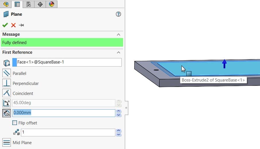
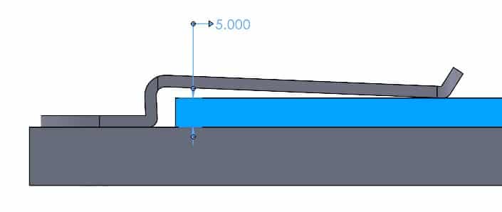
For this instance, we want the finish of the tab to freely bend in an upward and downward arcing motion as the thickness of the top plate changes. Therefore, the planar confront of the elevation plate will be the pick for our Reference Aeroplane. Use a Distance relation here and set the distance to zip. This zero-distance offset airplane acts as a direct replacement of a part face that ultimately moves. This allows for greater command over the placement of the external reference.
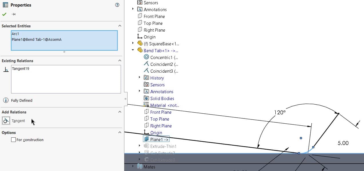
Drag the Rollback Bar below the feature containing the sketch that controls the overall shape. In almost cases, this volition be the first characteristic of the original part. Then, create a relation between the newly created airplane and the portion of the sketch that will contact the external reference in the assembly. In this case, I created a tangent relation betwixt the new airplane and the sketch fillet. For additional data about acceptable external reference types, see the SOLIDWORKS Help site accessible through the Assist dropdown in SOLIDWORKS.
Leave the sketch and drag the Rollback Bar to the end. Exit the 'Edit Part' to return to the assembly environs. At this betoken you lot can then select the function from the Feature Tree and the 'Make Part Flexible' Icon volition at present be selectable.
You will now be prompted to engage the flexible component by remapping the missing reference. (Some flexible components may require more than than 1 reference pick)
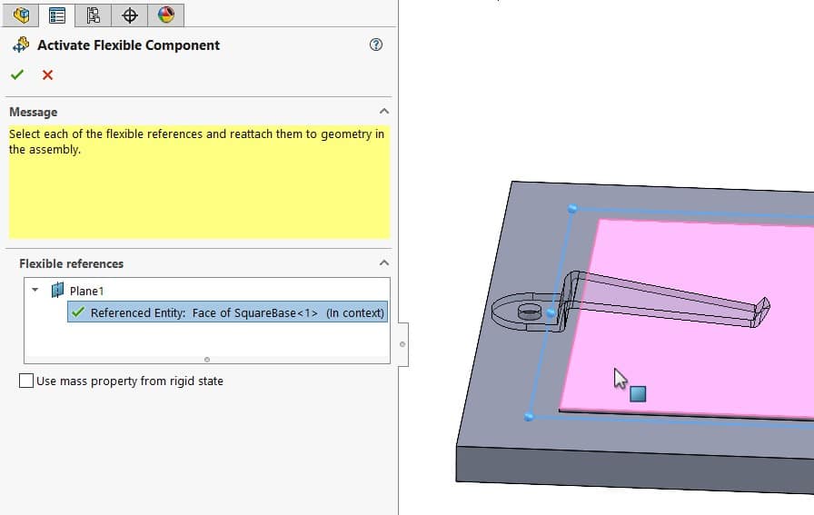
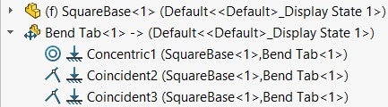
Here nosotros cull the top confront of the smaller plate and we receive a light-green cheque in the Flexible references window in the Holding Manager. Accept the choice and the assembly component now has a Flexible Component Icon in the Feature Tree as seen beneath.
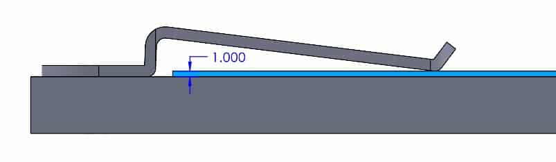
Annotation the automated repositioning of the part with changed in the associates.
Upon saving changes, you lot will now be able to insert this part into other assemblies with the available 'Make Role Flexible' control. Simply mate the office into identify, select the component from the Characteristic Tree, and cull the 'Mark Part Flexible' Icon from the popular-upwardly carte du jour.
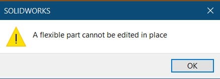
Additional notes regarding capabilities of this feature: While associates components may exist edited in-context, a flexible part cannot.
Should an in-context edit for a flexible role be required, select the flexible part from the Feature Tree once again and toggle off the 'Make Office Flexible' Icon. Edits can so exist fabricated prior to making the part flexible once again. Reference selections will prompt once more.
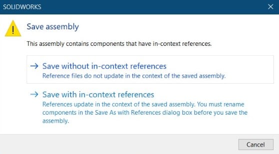
Lastly, when saving assemblies with in-context features, nosotros accept the choice to save with or without these in-context references. Saving with references requires you to edit the referenced file locations to forestall the in-context features from affecting other instances of the part.
This basic example highlights the overall process necessary for other scenarios to maximize the functionality of a flexible component. Please reference my colleagues blog introducing the update for the 2020 software release if you lot would like to learn more.
SOLIDWORKS 2020 What's New – Flexible Components (cati.com)
Thank you for reading and enjoy expanding your dynamic range in Assemblies!
Gabriel Rodriguez
Application Engineer
Computer Aided Technology, Inc.
Source: https://www.cati.com/blog/solidworks-make-part-flexible-how-to-modify-components-to-allow-flexibility/
Posted by: stevensonablents.blogspot.com
0 Response to "How To Make More Than One Part Move On Solidworks Animation?"
Post a Comment